Thrusters
![]()
![]()
|
Thrusters
|
|
|
Thrusters
As nearly everyone knows ships move by the engine turning a propeller, this acts like a screw in wood, when you turn the screw the thread cuts a path through the wood, in or out depending upon which way you are turning, if the thread is fine it takes a lot of rotation to move a small way, if the thread is coarse the screw moves further with each turn but it takes more effort to turn the screw. If you look at pictures of early propellers, some look a lot like wood screws, these days they look very different, but the principle is the same (OK things are a little more complicated, with high pressure behind the blade and low pressure in front, but the wood screw idea is easy to imagine), except of course water does not grip like wood so a lot of energy is wasted, the difference between the theoretical distance that the propeller would move in a solid and how far it actually moves through water (which varies) in one revolution, is known as propeller slip or just slip.
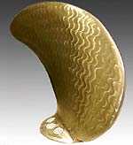
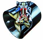
A modern 5 bladed controllable pitch propeller So we have a propeller providing thrust, but we need to accurately control the amount of thrust. From the wood screw analogy we know that if we turn the screw faster it moves through the wood faster. The problem with adjusting the speed is that it is awkward (which means expensive) to do quickly and accurately enough, to give the level of control required for a DP vessel. Another way is to change the pitch (think back to the effect of how far apart the threads are on a screw), a large pitch means large thrust and a small pitch mean small thrust, this is an easily achieved way of controlling the thrust output of a propeller. All that is needed are lots of different propellers, or a way of controlling the blade pitch on one propeller (which is what we do). The most common method of operation for DP vessels is to have an engine room providing large amounts of electrical power, with each thruster being driven by a constant speed A/C motor. This makes thruster installation a lot easier than having to have a diesel engine to drive each thruster, as it means all the power generating machinery can be in one area and electric cabling run to the various thruster compartments. The control of thrust output is implemented by using a controllable pitch propeller which turns at constant rpm but each blade rotates on command, from around -20 degrees pitch for full astern thrust. through zero pitch for zero thrust to +20 degrees pitch for full ahead thrust, each blade is interconnected so they all move the same amount at the same time. Advances in technology (which means expensive stuff gets cheaper) has allowed the use of variable speed A/C motors in some modern thrust units, adjustment of speed is effected by frequency adjustment in the supplied power. This means that the speed and therefore thrust of the propeller can be infinitely controlled up to a motor maximum, allowing very precise control of a fixed propeller. Fixed propellers are desirable as they are cheap(er), low maintenance and easier to calibrate to DP systems.
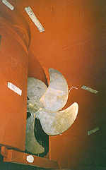
A single blade from a controllable pitch propeller Now that we can control the amount of thrust, we need to be able to point it in the direction we want. Conventional ships use rudders, situated behind their propeller to cause drag on the side that they want to turn towards, obviously the effectiveness of the rudder depends on the water flow past it. This works very well for conventional shipping (though not always, remember the navy ship that collided with London Bridge) but a DP vessel is designed for precise low speed maneouvering or remaining stationary where the rudder is totally inefficient. We need to be able to direct our thrust more effectively. There are 3 main types of propeller driven thruster, the normal propeller as found on every cargo ship, the tunnel thruster and the azimuthing thruster. The main propellers (normally 2 are fitted on offshore oilfield support type vessels) are situated as normal towards the stern, they are designed to counteract the fore and aft forces on the vessel.
A conventional propeller fitted to a cargo vessel Tunnel thrusters are propellers fitted in a tunnel mounted horizontally through the ship, often 2 or 3 forward and 2 aft, these combine to counteract the transverse and rotational forces.
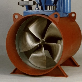
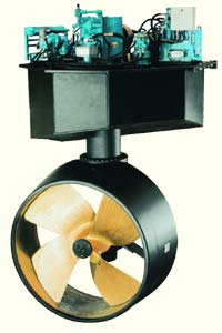
Tunnel thrusters, actual and diagrammatic Azimuth thrusters are propellers mounted on a vertical shaft that project below the vessel, the shaft (therefore the thruster) can rotate through 360 degrees, imagine an outboard motor secured from above, rather than bolted horizontally. An azimuth thruster can rotate and counteract forces from any direction, these are very popular, though they are complicated and require a lot of maintenance.
Azimuth thrusters, actual and diagrammatic You will notice that the azimuth thruster has a nozzle around the propeller, not all do but it is common. The nozzle is commonly called a Kort Nozzle (after the company that introduced it). Research has proven (for the mathematically minded the research was based on Bernouilli's continuity equation) that at slow speeds, the nozzle improves the efficiency of water flow (and hence of the propeller). At higher speeds, the additional drag of the nozzle structure negates the efficiency increase.
|